PROJECTS FOR EEE
IR Obstructer Using 555 Timer
We know that IC 555 is a popular timer chip used to make timer circuit. The 555 timer operates in three modes like monostable, astable and bistable modes. In monostable mode, the timer acts as a one-shot pulse generator. In astable mode, the timer acts as a free running multivibrator. And in bistable mode, the timer acts as a schmitt trigger. It has many applications in linear ramp generator, pulse width modulation, time delay generation and etc. in this article we are going see about IR obstructer using 555timer.
From the below circuit, here we are using 555timer where pin1 is connected to ground (GND) and pin2 is connected to pin6 which is threshold pin of timer. The pin3 is connected to base of a transistor BC547 whose emitter is connected to GND and collector is connected to power supply through IR diode / LED D1 and a Resistor. The pin4 of timer is connected to pin7 through resistor R2 of 1k again pin7 and pin5 are shorted together in between two capacitors C1 of 0.01µF, C2 of 0.01µF and a potential divider of 2.2k. The pin8 of the timer is connected to power supply.
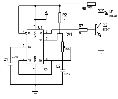
In this, the 555 timer used is in free running astable multi-vibrator mode at a frequency of 38 KHz and a duty cycle of about 60%. The said pulses drives a transistor Q2 the collector of which powers an IR diode D1 through 100Ω resistor from the power supply 6V DC. As the receiving unit of any T.V receives 38KHz pulses from its own remote, continuous stream of 38KHz pulses so generated by an external timer circuit superimposes and overrides the remote signal resulting in making the T.V remote sent pulses scrambled. Thus the T.V is not able to respond the required pulses from the T.V remote to take any action such as channel change, volume up, down etc.
Interfacing Matrix Keypad With 8051
A keypad is the most widely used devices of digital circuits, microcontrollers or telephone circuits. Many applications require large number of keys connected to a computing system. Provided that it for the most part holds numbers then it can additionally be known as a numeric keypad. In order to use it efficiently, we need a basic understanding of them.
How Matrix Keypad Works:
There are numerous techniques depending on the connection keypad with microcontroller, but the fundamental logic is same the columns are made as input and drive the rows making them as output. So as to detect which key is pressed from the matrix keypad, the row lines are to be made low one by one and read the columns.
Here we are going to see a 4×3 matrix keypad. It is 12 keys keypad consists of four rows and three columns. Assume that if row1 is made low, then read the columns. If any of the key in row1 is pressed then correspondingly the column 1will give low that is if second key is pressed in row1, then column2 will give low. Suppose, if we press one on keypad then D1 and D2 are switched ON makes the connection and displays the number on LCD display through microcontroller. Similarly, all keys will perform same operation as key one. We cannot press two keys at the same time. There should be a time difference between to press the key with one other.

Interfacing Matrix Keypad with 8051 Microcontroller:
From the circuit, pin 1.0 to pin 1.3 of port 1 of microcontroller are connected to rows of keypad and pin 1.4 to pin 1.6 of port 1 of 8051 microcontroller are connected to columns of keypad.
When the numbers pressed in the matrix keypad load corresponding logical state at the input of the microcontroller i.e., port 1. The program is so written that when say1111 is pressed then microcontroller delivers a logic high command at the controller output. This output high logic from the microcontroller is then fed to the relay driver IC input for ULN2003 output to go low to switch ON the corresponding relay that in turn switches on the load as per the password sent from the keypad. For example if 1111 is pressed the corresponding load 1 is switched ON and while it is pressed again 1111 it switches OFF. Accordingly all other loads are operated as per the passwords.
For example: 1. To switch on the 1st circuit breaker password is “1111”
2. To switch off the 1st circuit breaker password is “1111”
3. To switch on the 2nd circuit breaker password is “2222”
4. To switch off the 2nd circuit breaker password is “2222”

Audio Level Meter (VU-Meter) Using LM3915
The LM3915 is similar as LM3914 dot/bar display, where in LM3915 the values can be adjusted logarithmically and is suitable for log estimations as logarithmic bar graph driver. This detects simple analog voltage levels and powers ten LEDs, supplying a logarithmic 3dB/step analog display. LED current drive is managed and programmable, dispensing with the requirement for current constraining resistors. One pin changes the display from a bar graph to a moving dot display.
The entire display system can operate from a single supply as low as 3V or as high as 25V. Multiple devices can be cascaded for a dot or bar mode display with a range of 60 or 90 dB. LM3915s can also be cascaded with LM3914s for a linear/log display or with LM3916s for an extended-range VU meter.
The LM3915 displays are used in audio applications, power meter and RF signal strength meters. And these displays are suited for signals with wide dynamic range, for example audio level, power and etc. Let’s see an application, an audio level meter using LM3915.
Audio Level Meter (VU-Meter) Using LM3915:
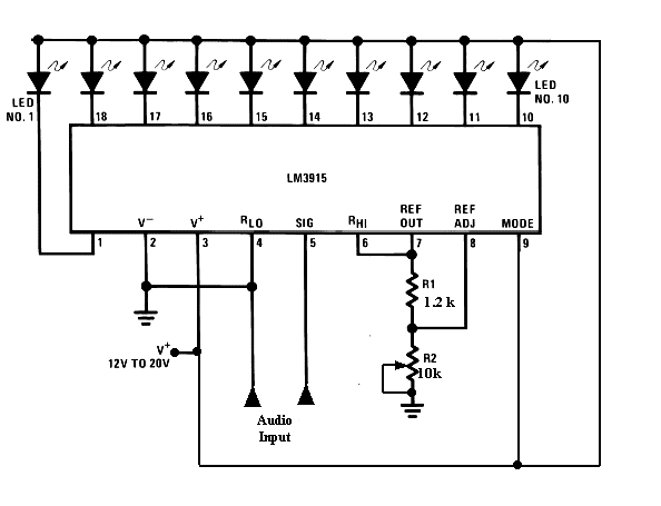
This circuit uses just one IC and a very few number of external components. It displays the audio level in terms of 10 LEDs. The input voltage can vary from 12V to 20V, but we using only 12V of voltage. The IC contains an adjustable voltage reference and an accurate ten-step voltage divider. The high-impedance input buffer accepts signals down to ground and up to within 1.5V of the positive supply. Further, it needs no protection against inputs of ±35V. The input buffer drives 10 individual comparators referenced to the precision divider. Accuracy is typically better than 1 dB.
Using the dot mode, the LED illuminated represents the instantaneous value of the audio wave form. Both peak and average levels can be easily observed. Since the dot will be constantly moving, the LED’s are run at 30mA for sufficient power. The full-scale reading is 10volts; that is easily adjusted by changing resistor R2. The LM3915 signal input can with stand signals up to 35 volts. If there is a chance that the audio input could exceed this range, either attenuates it or include enough series resistance to limit the current to 5mA.
LM3914 – Features & Working
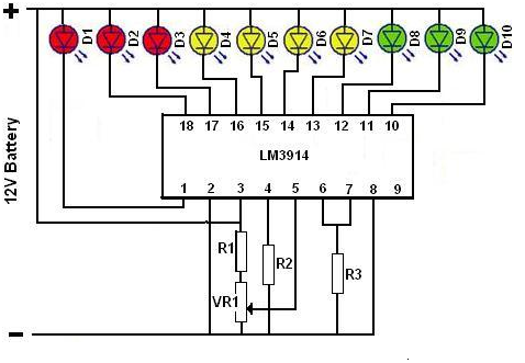
The LM3914 dot/bar display driver is an integrated circuit (IC). The LM3914 can sense the analogue voltage levels and sends that voltage levels to a display of ten LEDs or LCDs, giving a linear analog display. A single pin changes the display from a moving dot to a bar graph. The internal voltage of display driver is from 1.2V to 12V. The driver circuit can drive LEDs of many colors or low-current incandescent lamps which shown is in figure.
Features:
- Expandable to displays of 100 steps
- Internal voltage reference from 1.2V to 12V
- Operates with single supply of less than 3V
- Inputs operate down to ground
- Output current programmable from 2mA to 30mA
- No multiplex switching or interaction between outputs
- LED driver outputs are current regulated, open-collectors
- Bar or dot display mode externally selectable by user
- The internal 10-step divider is floating and can be referenced to a wide range of voltage
Working of LM3914:
The workings of the LM3914 are quite simple. It has a ten step voltage dividers with an adjustable voltage reference. Here the IC can act as a basic voltmeter. The resistors R1 and R2 work as a voltage divider and the voltage across R2 is the range of which the meter will display. For example, if voltage across R2 is 1.2V, then the difference displayed between LEDs 1 and 10 will be ~1.2V. The LM3914 has two modes, DOT mode and BAR mode. In DOT mode operation only one LED is ON at a time. The BAR mode is achieved by connecting pin 9 to the positive voltage then all LEDs are ON at a time. In BAR mode the current consumption would be increased by an amount depending on the number of LEDs turned on. By changing the values of resistor R3, we can change the brightness of the LEDs or LCDs. If the resistance of the R3 is high then the brightness will reduce. When the resistance of the R3 is low then the brightness of the LED will increase.
How BCD to 7 Segment Decoder Works?
A seven segment display is the widely used electronic display device that can display digits from 0-9. We call it as seven segment display because it is divided into seven segments. They are available in common anode mode and common cathode mode. The cathode and anodes are LED’s arranged in straight line form. If LED’s cathode is given negative and anode is given positive then it glows. Common anodes are connected to series of resistors of 470Ω and cathodes are connected to common ground, other end of resistors is connected to input to see how the segment is working.
When the input is high then the common negative is also low then the no LED glows. When logic high is given then the current pass through anode and reaches LED through resistor and it gets back to the ground. Then it makes the LED to glow. Example for displaying 7 we need to make the first 3 probes as high. These 0 and 1 comes from the micro controller.

Features of 7-Segment Display:
- Excellent Appearance
- High peak current
- Intensity and color selection option
- Excellent for long digit string multiplexing
- Design flexibility
Working of BCD to 7-Segment Decoder:
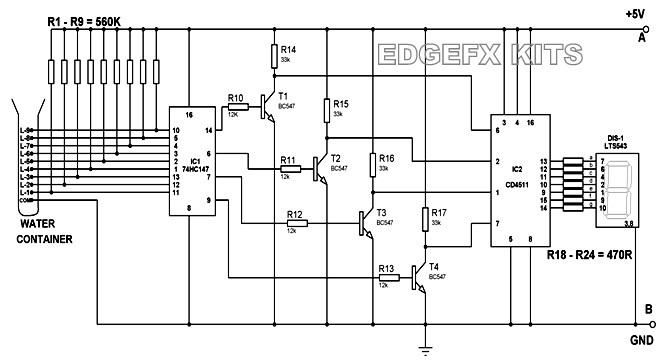
Here is a digital version of the water-level indicator circuit. It uses a 7-segment display to show the water level in numeric form from 0 to 9. The circuit works off 5V regulated power supply. It is built around priority encoder IC 73HC137 (IC1), BCD-to-7-segment decoder IC CD3511 (IC2), 7-segment display LTS533 (DIS1) and a few discrete components. Due to high input impedance, IC1 senses water in the container from its nine input terminals.
The inputs are connected to +5V via 560KΩ resistors. The ground terminal of the sensor must be kept at the bottom of the container. IC 73HC137 has nine active-low inputs and converts the active input into active-low BCD output. The input L-9 has the highest priority. The outputs of IC1 9, 7, 6, 13 are fed to IC2 via transistors T1 through T3. This logic inverter is used to convert the active-low output of IC1 into active-high for IC2. The BCD code received by IC2 is shown on 7-segment display. Resistors R18 through R23 limit the current through the display.
When the tank is empty, all the inputs of IC1 remain high. As a result, its output also remains high, making all the inputs of IC2 low. Display at this stage shows ‘0’, which means the tank is empty. Similarly, when the water level reaches L-1 position, the display shows ‘1’ and when the water level reaches L-8 position, the display shows ‘8’. Finally, when the tank is full, all the inputs of IC1 become low and its output goes low to make all the inputs of IC2 high. Display now shows ‘9,’ which means the tank is full.
BCD to 7-Segment Decoder Circuit
No comments:
Post a Comment